SMARTUNIFIER Configuration
Information Models
What Information Models are and how to create them is described in the chapter Information Models.
Information Model - Equipment (Circutor)
The first step is to create an Information Model that represents the Equipment data structure.

Structure of the Circutor Information Model:
Complex Variable DeviceData
Variables represent the Equipment parameters
ID |
Node Type |
Data Type |
|---|---|---|
DeviceData |
Variable |
DeviceDataType |
DeviceData/phaseVoltageL1 |
Variable |
Int |
DeviceData/currentL1 |
Variable |
Int |
DeviceData/frequencyL1 |
Variable |
Int |
Note
The group function allows you to combine logical entities into paths. You can use existing naming conventions and styles for naming equipment to organize the configuration components. This simplifies the structuring and management of configurations.
Hint
It is recommended to use the same “Group” name throughout the scenario. For example, to identify the created Artifacts for this scenario, the group name “demo.modbus2influx” is used.
Information Model - InfluxDB
There must be also a second Information Model for the InfluxDB.

Structure of the InfluxDB Information Model:
Complex Variable ModbusData represent the name of the database table
Variables represent the database columns, matching the Equipment parameters
ID |
Definition Type |
Data Type |
|---|---|---|
ModbusData |
Variable |
ModbusDataType |
ModbusData/phaseVoltageL1 |
Variable |
Float |
ModbusData/currentL1 |
Variable |
Float |
ModbusData/frequencyL1 |
Variable |
Float |
Note
In this case the Float Variable is used, to allow for a more precise input into the InfluxDB
Communication Channels
What Communication Channels are and how to create them is described in the chapter Communication Channels.
Communication Channel - Modbus
Next step is to create a Communication Channel for the Equipment.
1.) Enter values for Group and Name like in the screenshot below.
2.) Select the “Model” for the Equipment as the Information Model connected to this Channel (1).
3.) Select “Modbus Tcp Client” as the Channel Type (2).
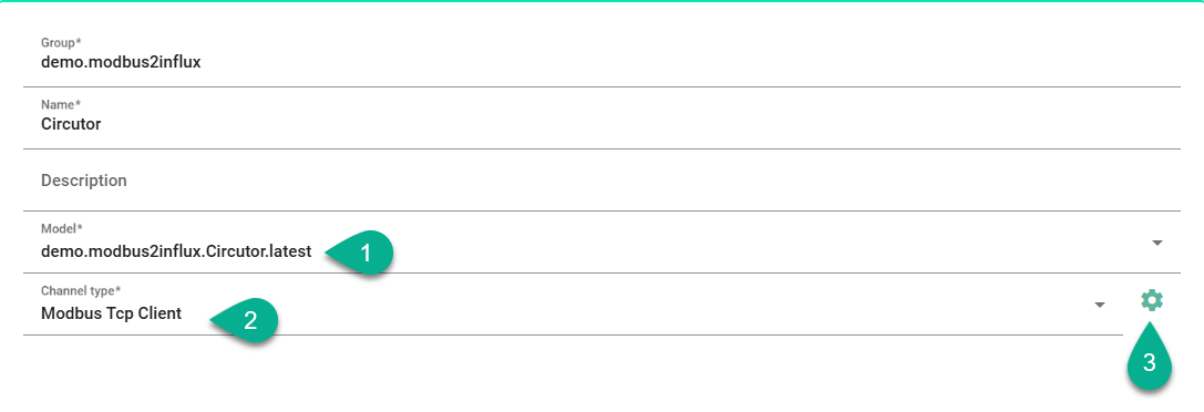
4.) Click the configuration button for the Modbus Tcp Client configuration (3).
5.) Set the “IP” (1) and the “Port” (2) of the Modbus/TCP Client.
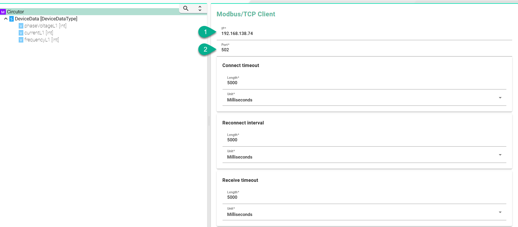
6.) Save the new Communication Channel.
Hint
What Modbus is and how to use it is described in our User Manual Modbus.
Communication Channel - InfluxDB
The next step is to create a Channel for the Influx Data Model.
1.) Enter values for Group and Name like in the screenshot below.
2.) Select the “Model” for InfluxDB as the Information Model connected to this Channel (1).
3.) Select as Channel Type the “InfluxDB v2” (2).

4.) Click the configuration button for the InfluxDB v2 configuration (3).
5.) Set the “URL” (1) and the “Name” (2) of the InfluxDB.
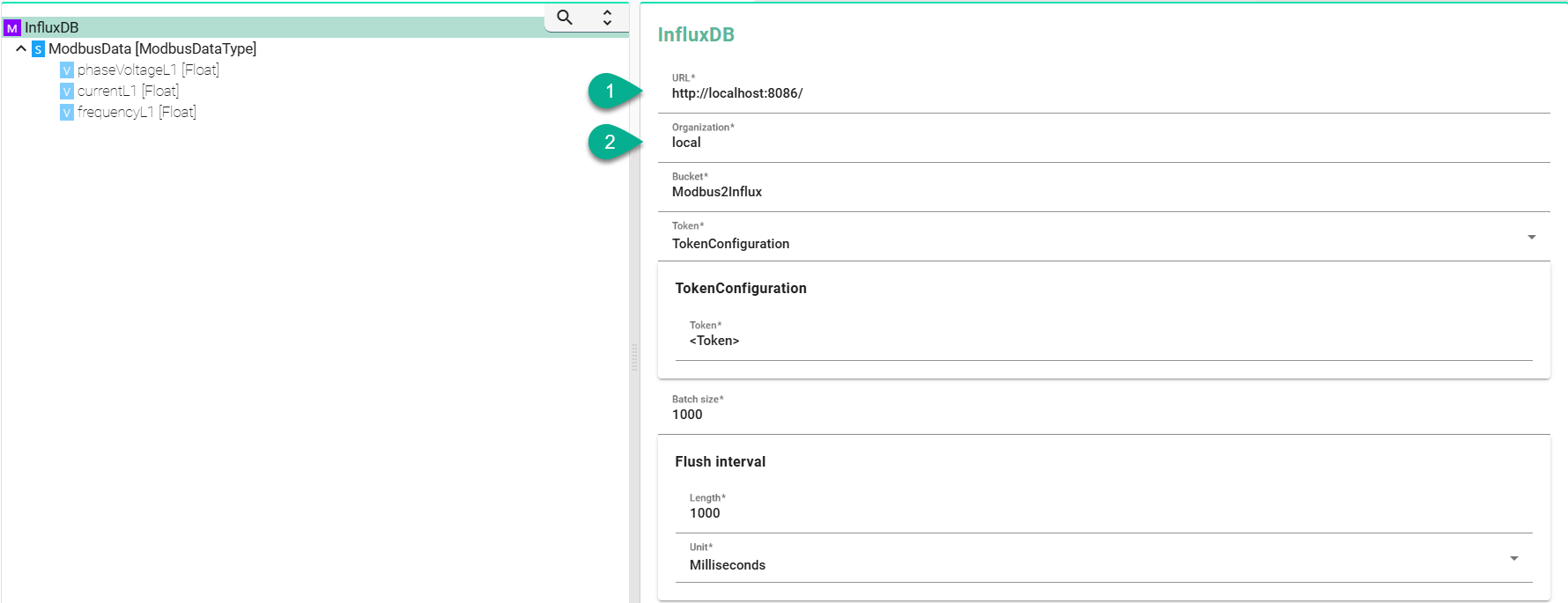
6.) Save the new Communication Channel.
Hint
What InfluxDB v2 is and how to use it is described in our User Manual InfluxDB v2.
Mapping
After the creation of Information Models and their dependent Communication Channels, the next step is to create the Mapping. What Mapping is and how to create it, is described in the chapter Mappings.
1.) Enter values for Group and Name like in the screenshot below.
2.) Select the Information Models created earlier. Click the “Add” button (1) and select the InfluxDB Information Model. Enter a Short name for it, e.g., “DB”.
3.) Click again the “Add” button (1) and select the Equipment Information Model. Enter a Short name, e.g., “equipment”.
4.) Next, add a Rule to the Mapping. Click the “Add Rule” button (2) and select “Single Rule” (3).

5.) Enter a Name for the new Rule like “ModbusToInflux”.
6.) Click on the Code Editor “<>”.
7.) For the demo Version, copy the following code.
Circutor.DeviceData.phaseVoltageL1 mapTo {
  variable=>
  InfluxDB.ModbusData.phaseVoltageL1:=div(toFloat(variable),10)
}
Circutor.DeviceData.currentL1 mapTo {
  variable=>
  InfluxDB.ModbusData.currentL1:=toFloat(variable)
}
Circutor.DeviceData.frequencyL1 mapTo {
  variable=>
  InfluxDB.ModbusData.frequencyL1:=div(toFloat(variable),10)
}
8.) Compile the Rule and Save the new Mapping.

Device Type
The next step is to assign the Mapping to a new Device Type. What Device Type is and how to create it, is described in the chapter Device Types.
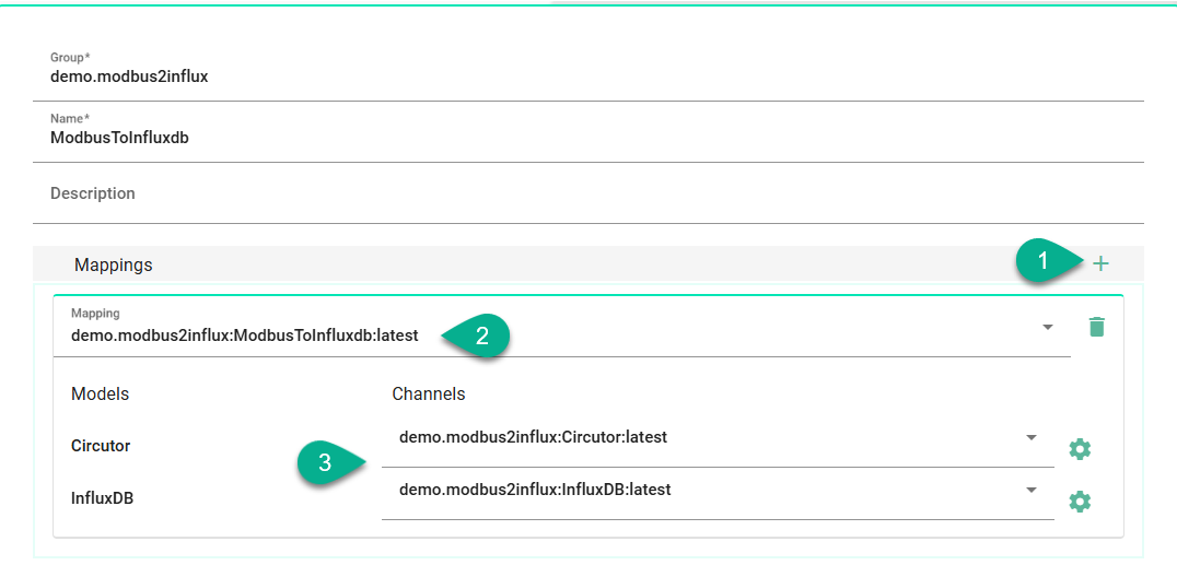
1.) Enter values for Group and Name like in the Screenshot below.
2.) Click the “Add Mapping” button (1).
3.) Select the Mapping “demo.modbus2influx:ModbusToInfluxdb:latest” previously created (2).
4.) Assign the correct Channels to the Information Models (3).
5.) Save the new Device Type.
Instance
Last step of this Scenario is the creation of the Instance. What Instance is and how to create it, is described in the chapter Communication Instances.
1.) Select the Device Type “demo.modbus2influx:ModbusToInfluxdb:latest” previously created (1).
2.) Values for Group and Name are already set from the Device Type. Although, we recommend changing the Name.
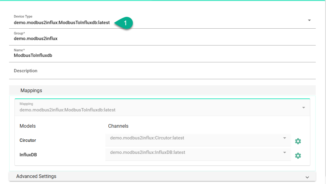
3.) Save the new Instance.
After all steps have been executed the Instance “demo.modbus2influx:ModbusToInfluxdb:latest” is fully configured and ready for Deployment.
Deployment
What Deployment is and how to create it, is described in the chapter Deployment.
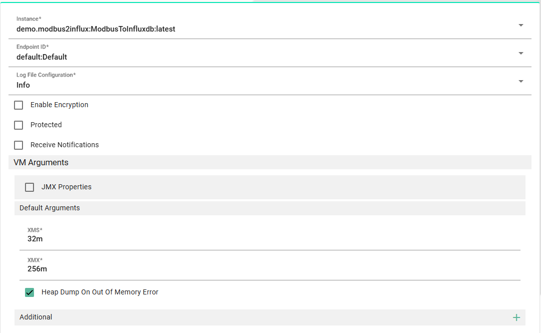
1.) Add a new “Local” Deployment. This deploys the Instance on the machine you are working on.
2.) Select the Instance “demo.modbus2influx:ModbusToInfluxdb:latest” previously created.
3.) For “EndpointId” choose “Default” location.
4.) For “LogfileConfiguration” set “Info”.
5.) Save the new Deployment.
6.) Go to Deployment Endpoints section and click on the “Start” button for the “Default” Endpoint.

7.) Return to Deployment section and click on the “Deploy” button.

8.) Click the “Start” button.

The Instance is now running on the local machine.
