Instance Setup
A SMARTUNIFIER Instance is a dynamically created application that can be deployed to any suitable IT resource (e.g., Equipment PC, Server, Cloud), and which provides the connectivity functionality configured. Therefore, a SMARTUNIFIER Instance uses one or multiple Mappings, selected Communication Channels and Information Models.
Information Models
Within the SMARTUNIFIER an Information Model describes the communication related data that is available for a device or IT system. One device or one IT system therefore is represented by one Information Model.
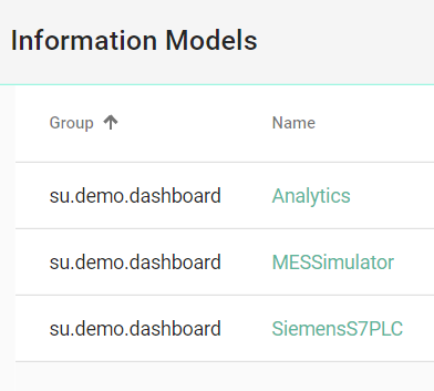
The Information Model perspective lists the information models currently configured within the SMARTUNIFIER Manager:
Analytics
MES Simulator
Siemens S7PLC
Analytics
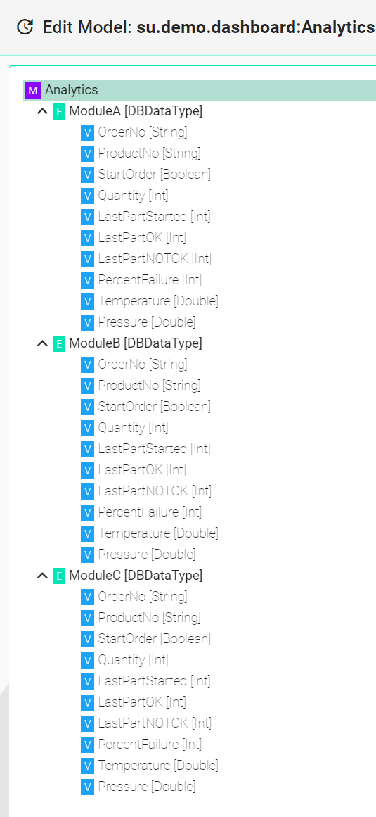
The Analytics represents the Influx database Information Model that stores data from the PLC of the production equipment (Equipment Simulator). The data provided by the Equipment Simulator (PLC) is stored using the SMARTUNIFIER in the Influx database and the overall process can be viewed on the Grafana dashboard. As seen below, the data is structured for each production module.
MES Simulator
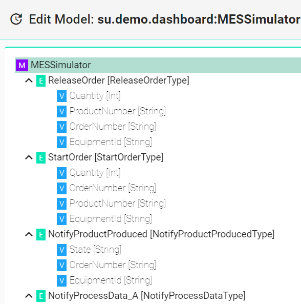
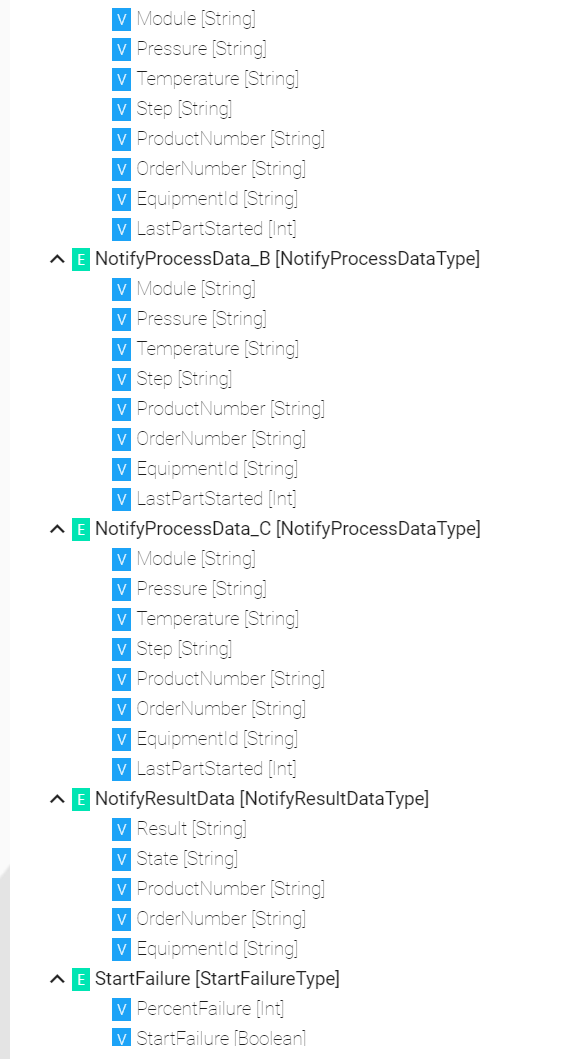
The MES Simulator Information Model represents the MES structure. It maps the production process flow, as seen below.
Siemens S7 PLC
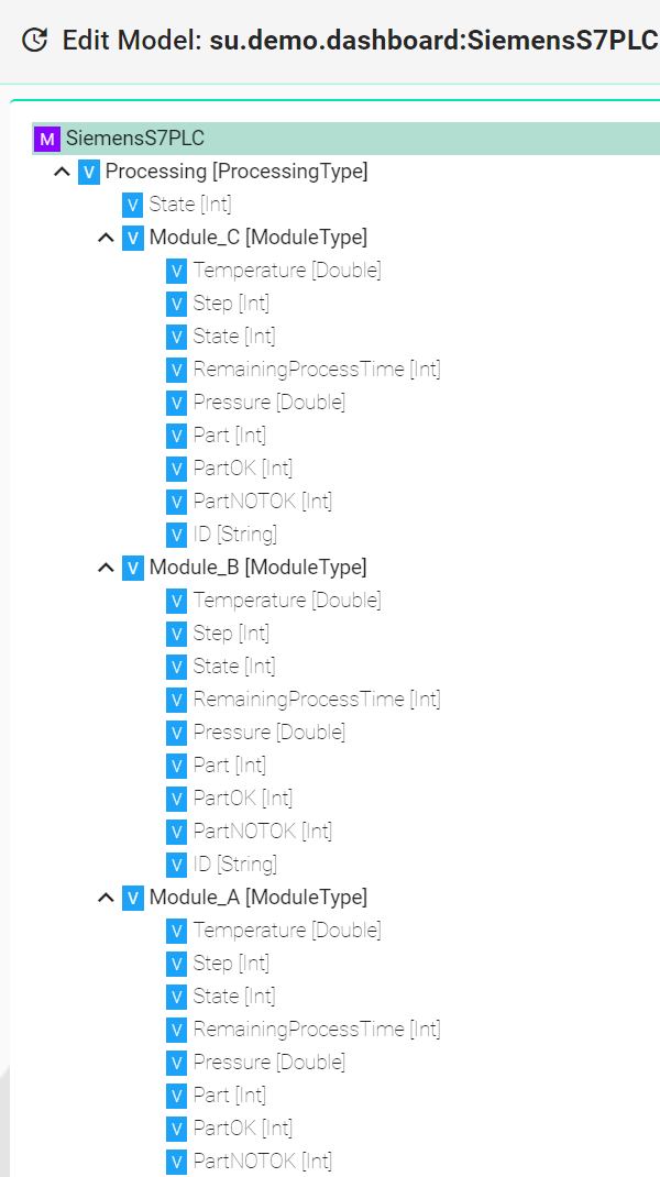
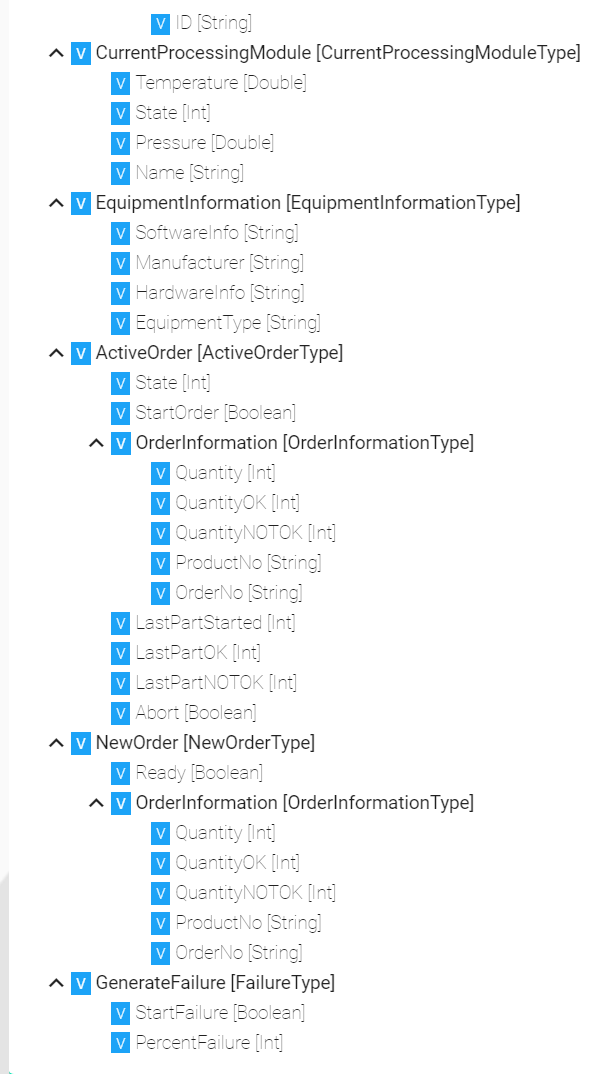
The Siemens S7 PLC Information Model represents the PLC blocks structure. As seen below, the Model contains the input and output data for each production module.
Mappings
The Mapping represents the SMARTUNIFIER component that defines when and how to exchange/transform data between two or multiple Information Models. In other words, it is acting as a translator between the different Information Models. One Mapping consists of one or multiple Rules. A Rule contains a Trigger, which defines when the exchange/transformation takes place, and a list of actions that are defining how the exchange/transformation is done.
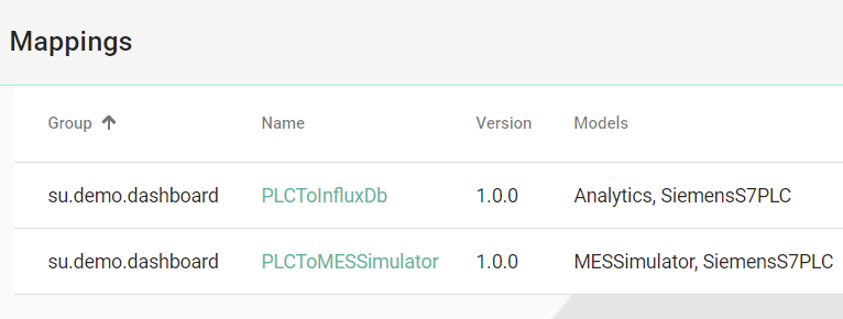
The Mapping perspective lists the Mappings currently configured within the SMARTUNIFIER Manager:
PLC to InfluxDb
PLC to MES Simulator
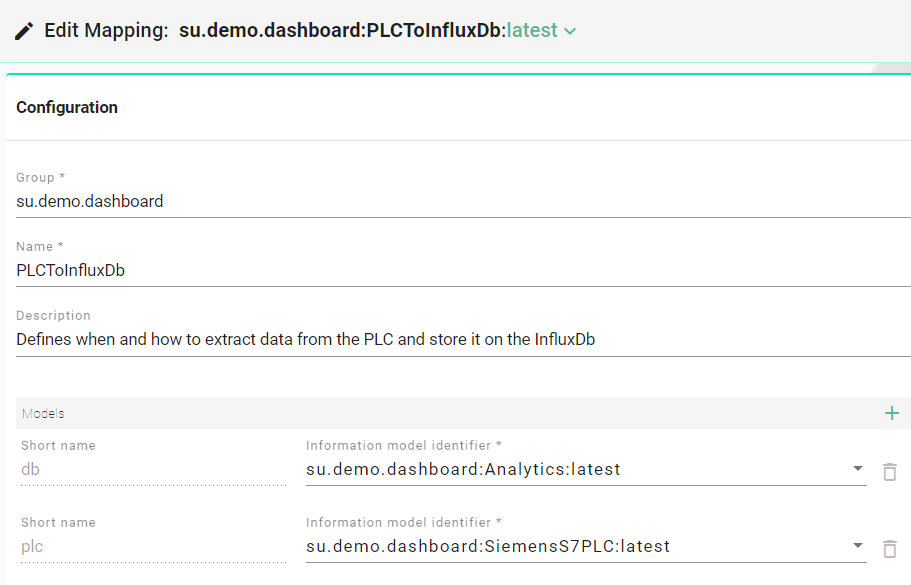
PLC to InfluxDb
This Mapping defines when and how to extract data from the PLC of the production equipment (Equipment Simulator) and store it on the InfluxDb.
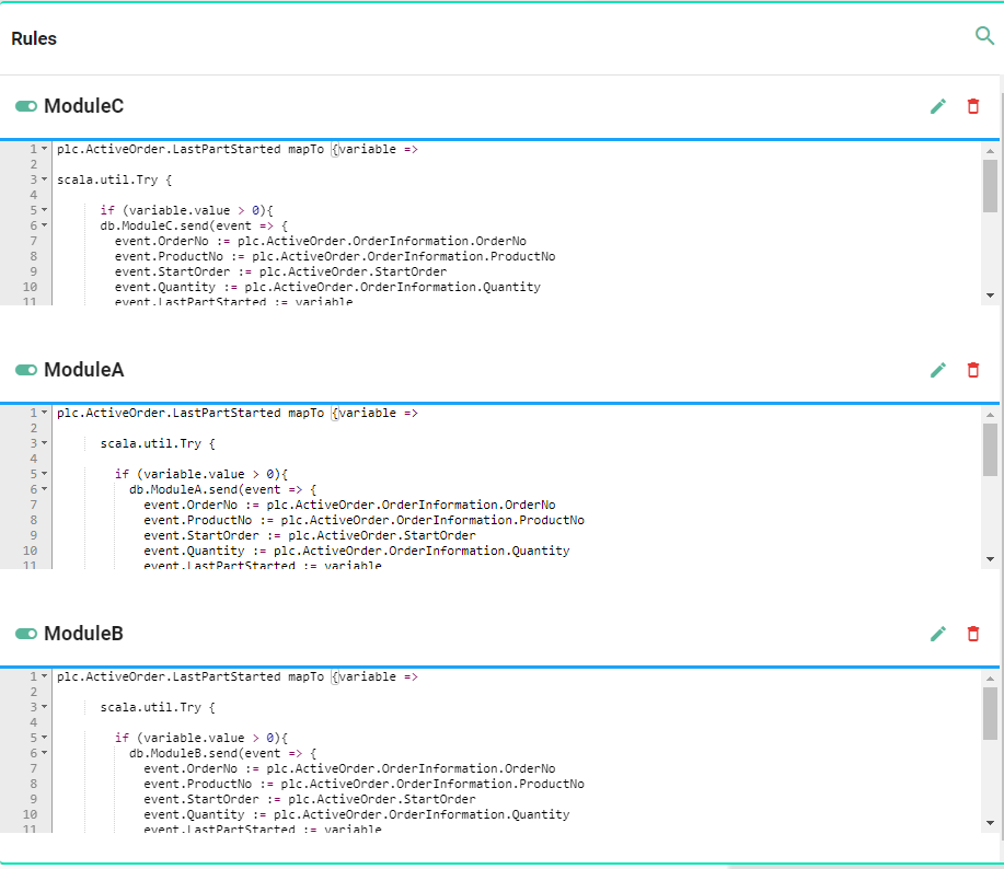
As seen above, for each production module, the rules created with Scala code lines define how the data exchange takes place.
PLC to MES Simulator
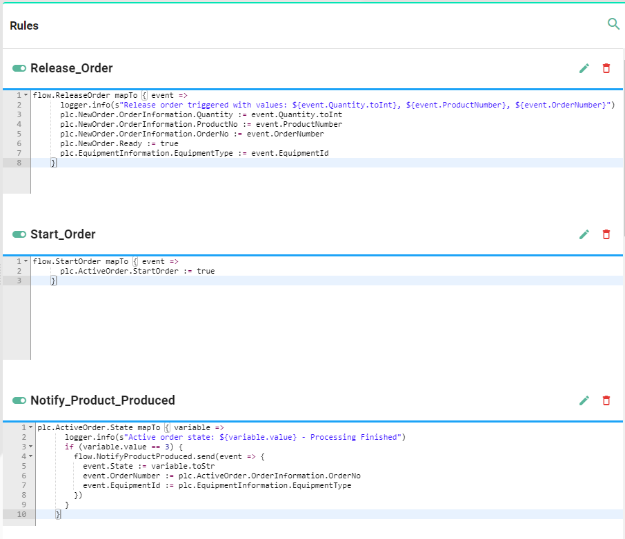
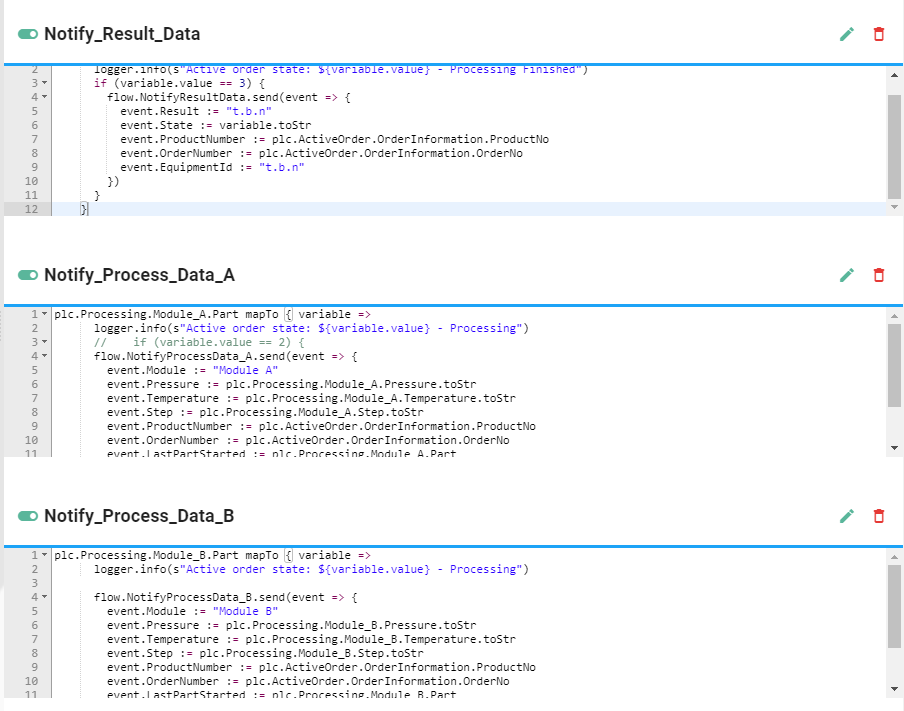
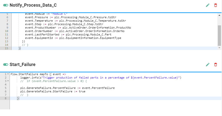
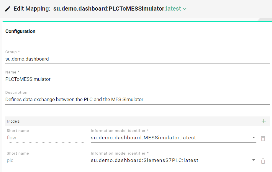
This Mapping defines data exchange between the PLC of the production equipment (Equipment Simulator) and the MES Simulator (Node-Red Dashboard).
As seen below, for each production process, the rules created with Scala code lines define how the data exchange takes place.
